Credit by Dennis H.
This time we can take a closer look at the PROVerXL 4030 CNC in the Improved V2. A recirculating ball spindle movement system and stepper motors with a closed control circuit make a hobby desktop milling machine sit up and take notice. The machine with 400 mm x 300 mm working area comes mostly pre-assembled, so that you can be ready for use in less than 1 hour.
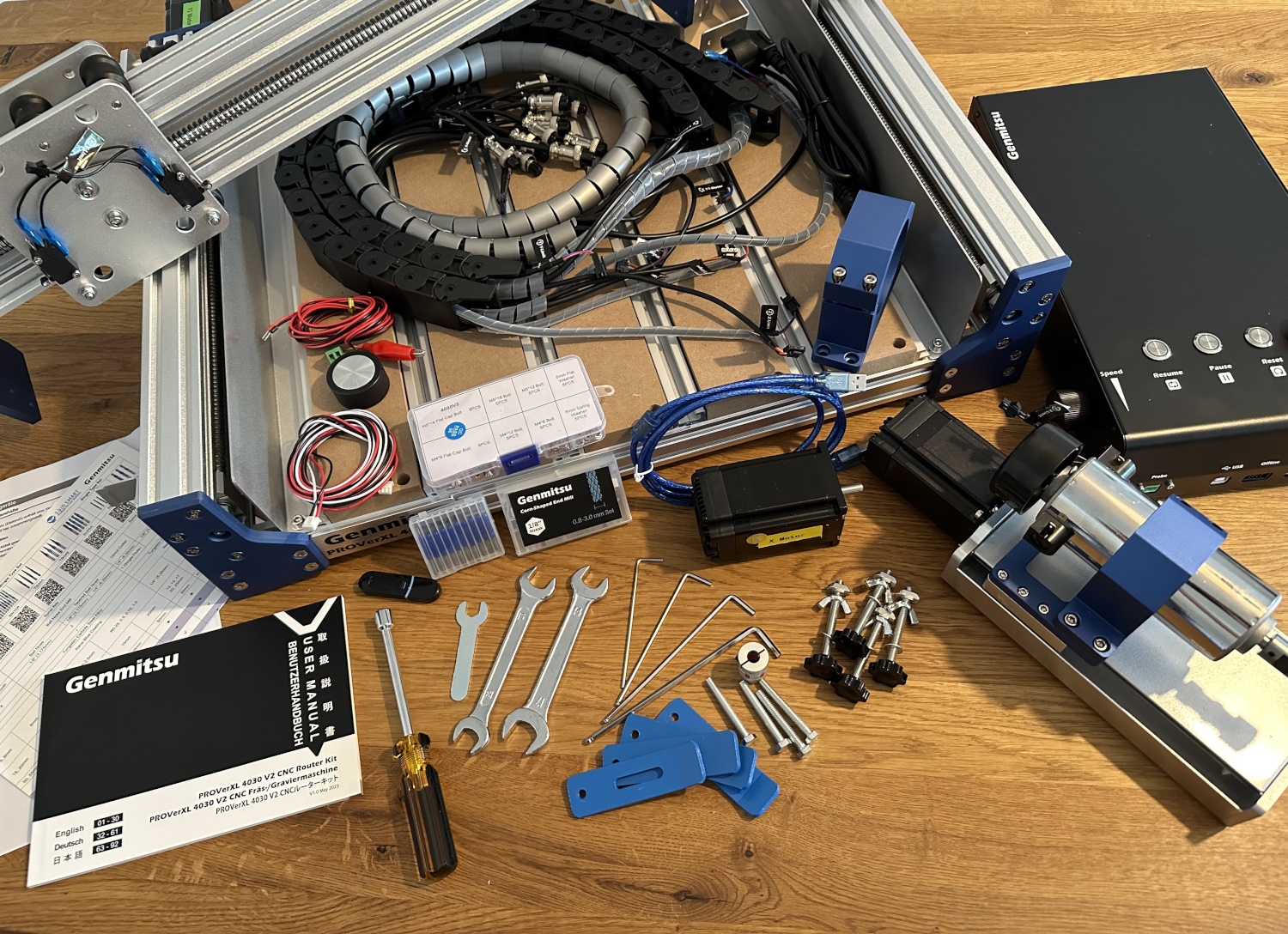
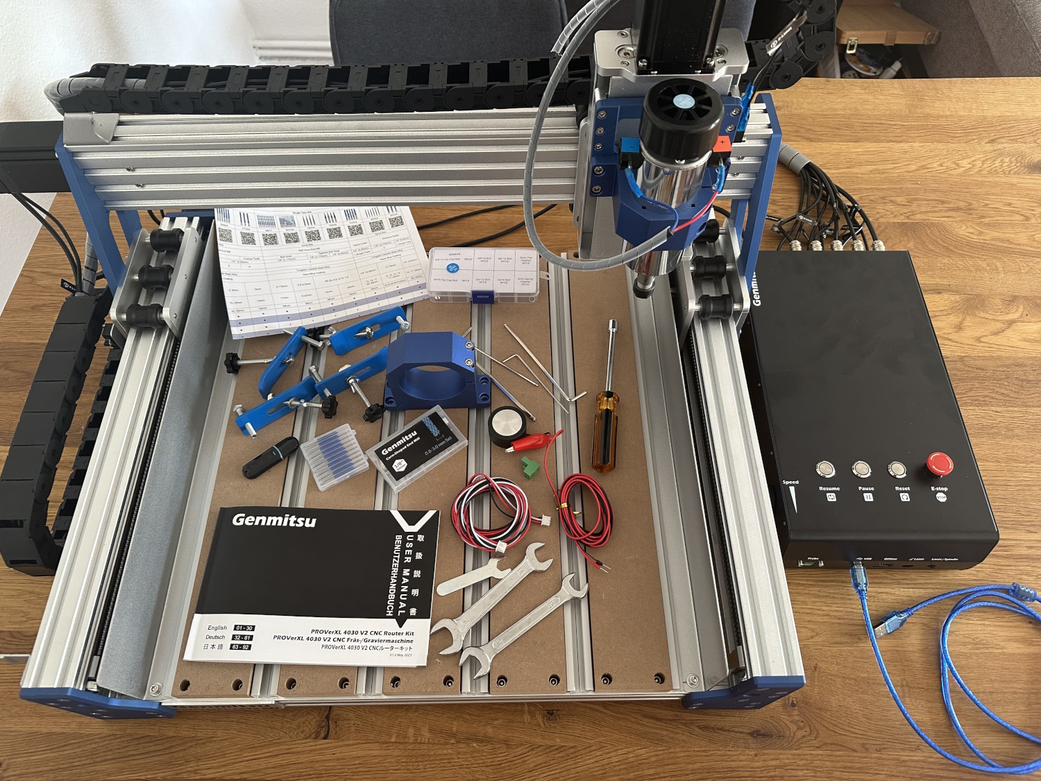
Scope of delivery
The 4030 V2 from SainSmart is specified with the following data:
| Workspace | 400 x 300 x 110 mm |
| Dimensions | 742 x 489 x 605 mm |
| Set-up time | 25-30 min |
| Extensions | 6060 & 1313 possible |
| Stepper | NEMA23 76mm (closed loop) |
| Movement system | 1204 Ball Screw |
| Frame | Metal construction with hybrid sacrificial plate |
| Control | GRBL 1.11h |
| Feed | 5000 mm/min |
| Accuracy | Circular path: ≤ ±0.05 mm; Rectangle: ≤ ±0.02 mm |
| Repositioning accuracy | ≤ ±0.05 mm |
| Stepper motor drive | WSD6056DN56 |
| Spindle | max 400W 10000 RPM |
| Spindle Clamping | DC, 0-48V |
| Power supply | 48V 7A & 24V 8A |
In addition to the components necessary for the construction of the 4030 V2, the following accessories are included:
- 3.75 GB USB stick (manual, software, test files)
- Tools (open-end wrenches, Allen keys and screwdrivers)
- 4x retaining clips for T-slots
- 10x V bit engraving cutters (wood, metal, etc.)
- 10x Multi-Cutting Milling Cutters (Wood, PCBs)
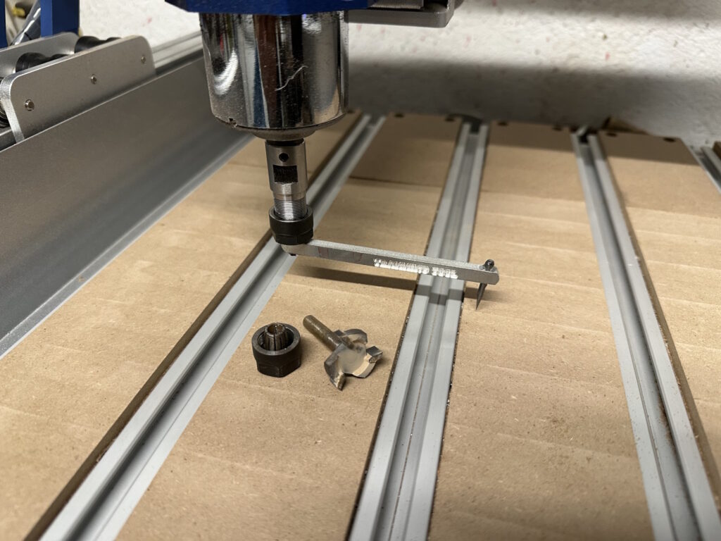
- 65 mm spindle holder
- 1x Replacement Fuse
- 1x USB cable
- Z-Measuring Plate
- Adapter cable for laser operation
- Multilingual User Manual
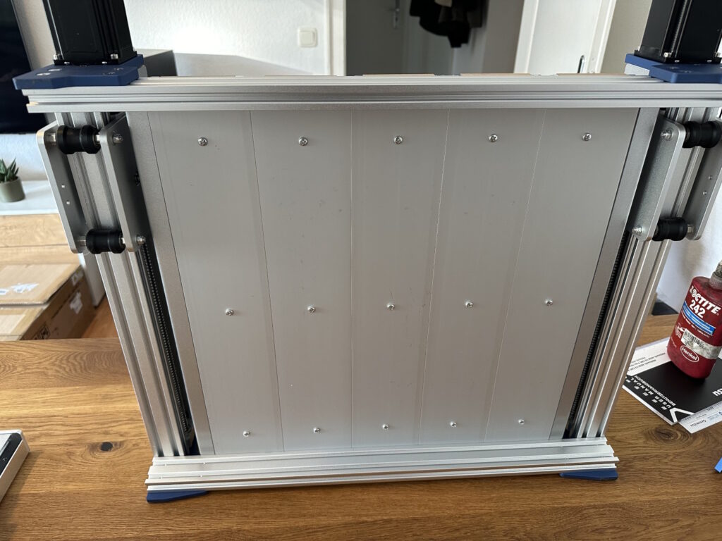
Overall, everything looks very solid and robust. Most of the components are made of aluminum, the Hybrid Spoilboard consists not only of thin T groove strips, but of wide profiles on which the MDF is screwed on. In other words, the space between the outer frames is completely closed:
The following profiles are used:
| Y Axis/Frame | 40 x 80 mm (internal ball screw) |
| X axis | 40 x 80 mm (internal ball screw) |
| X Frame | 20 x 40 mm |
| Z axis | 12 mm round guides + plate and edge components |
Assembly
In the previous pictures you could already see the degree of pre-assembly. The entire basic construction, i.e. frame, hybrid sacrificial plate and Y-axis drive with limit switches, is already a unit. By the way, hybrid sacrificial board stands for the combination of T-slots for retaining clips and normal MDF wood. The same applies to the bridge for X and Z. This is also mostly pre-assembled, only the stepper motor and the wiring harness are missing. The Z module joins in and is also pre-assembled as a single unit. 4 screws and the fastening is done. The assembly time of about 30 minutes, as stated, is actually no problem.
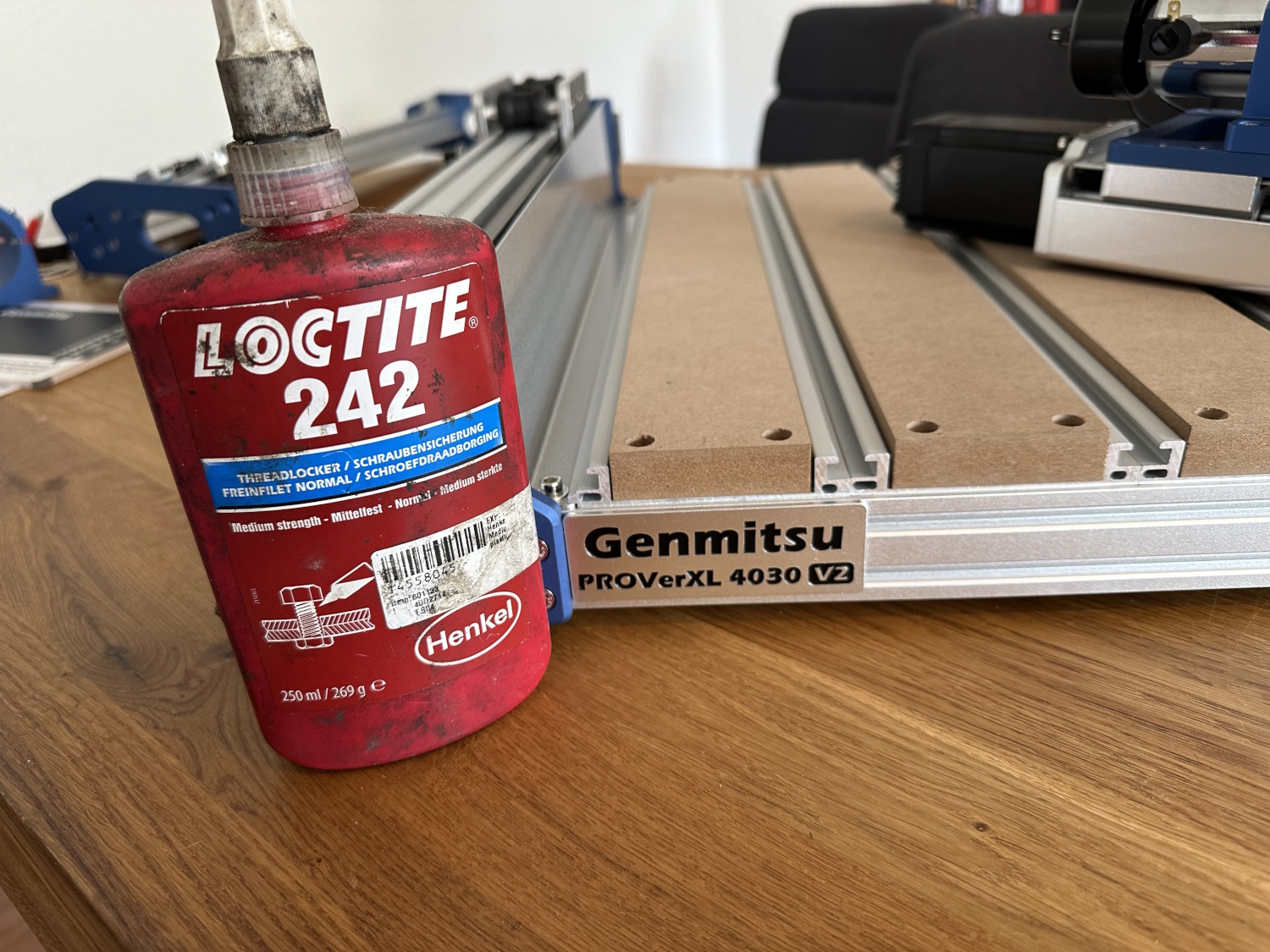
As with all CNC machines, I recommend using the screws with threadlocker, I use Loctite 242, but there are plenty of other alternatives.
Let's start with the construction. In the first step, the two Y-axis motors are aligned. The spindle can be rotated using the included screwdriver and must be brought to the same size on the right and left. Which measure is secondary, it is just necessary to set the same starting point for both sides. During a test milling, a Y stepper motor dropped out for an unknown reason, while all other axles continued to drive merrily. The machine was not switched off and wounded properly. One Y side was completely fixed or still and the other Y side had no difficulties thanks to the power of the NEMA23. So it may well be that you have to repeat this step again – in all tests, I only came across this phenomenon once. After I unplugged and reconnected the current from the affected stepper motor, the red lamp went out and you could continue without losing position... First of all, let's continue with the construction:
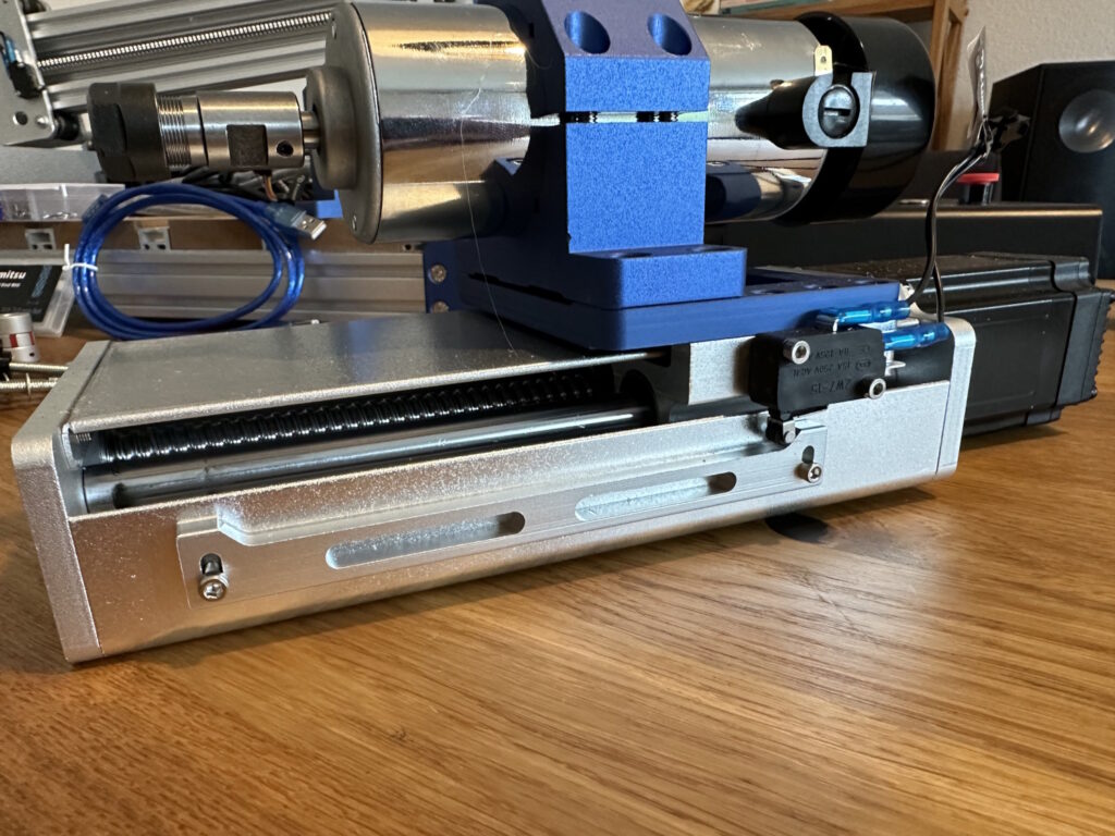
In the second step, the bridge is already being set up. Due to a contrasting edge on the bridge itself and a holder on each of the base plate, you only have to attach it and push it onto the stop. 8 screws make the connection. The Z axis is then mounted on the carriage as an entire unit. 4 screws are used for fastening, which are very easy to reach through an additional hole.
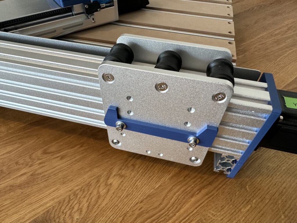
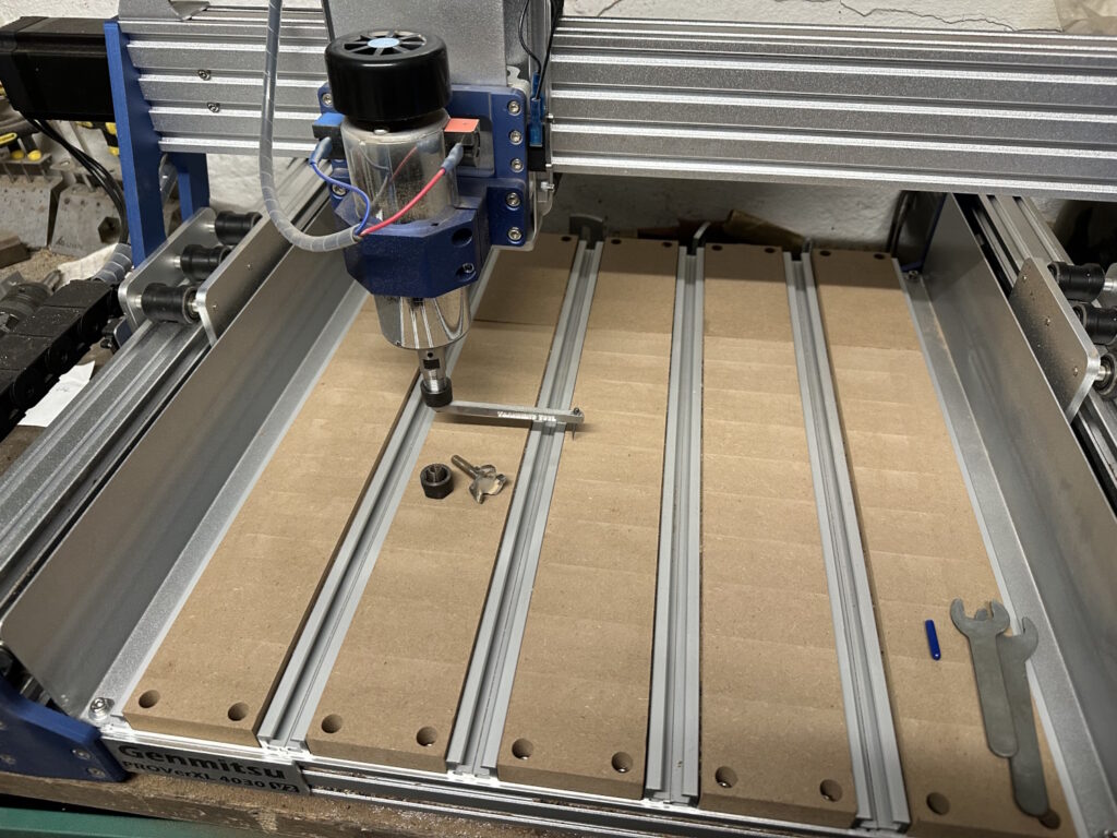
We continue with the X-axis stepper motor. Due to the closed control loop, i.e. the query whether the required path is really being taken, and the increased performance, the motor is significantly larger than, for example, the 3020 Pro Max. All you need for attachment is the coupling and four screws. For alignment, I first tightened the clutch and the screws slightly and only tightened them after everything was attached.
In preparation for the wiring harness, which, by the way, is fortunately delivered completely pre-assembled and ready for installation, a few brackets still have to be mounted. Afterwards, the drag chains are first mounted, then all plugs can be connected according to their labeling. These include the limit switches in Z, X and Y, which are already connected by Y cable, the stepper motors with two plugs each and the spindle motor itself.
The last pictures show how the roller tension can be adjusted. The axles can be moved by means of a socket wrench, so that you can access the lower rollers or its eccentric screw by means of the small open-end wrench. All reels should be firm and not spin freely. Do this with feeling, too high a contact force causes resistance and increased wear. Too little force causes play in the axle – a little dexterity is required here. At this point, I would have liked to see a linear guide system, but we will see how the rollers perform later in the tests. Apparently a first weak point on the 4030, with the otherwise extremely robust design.
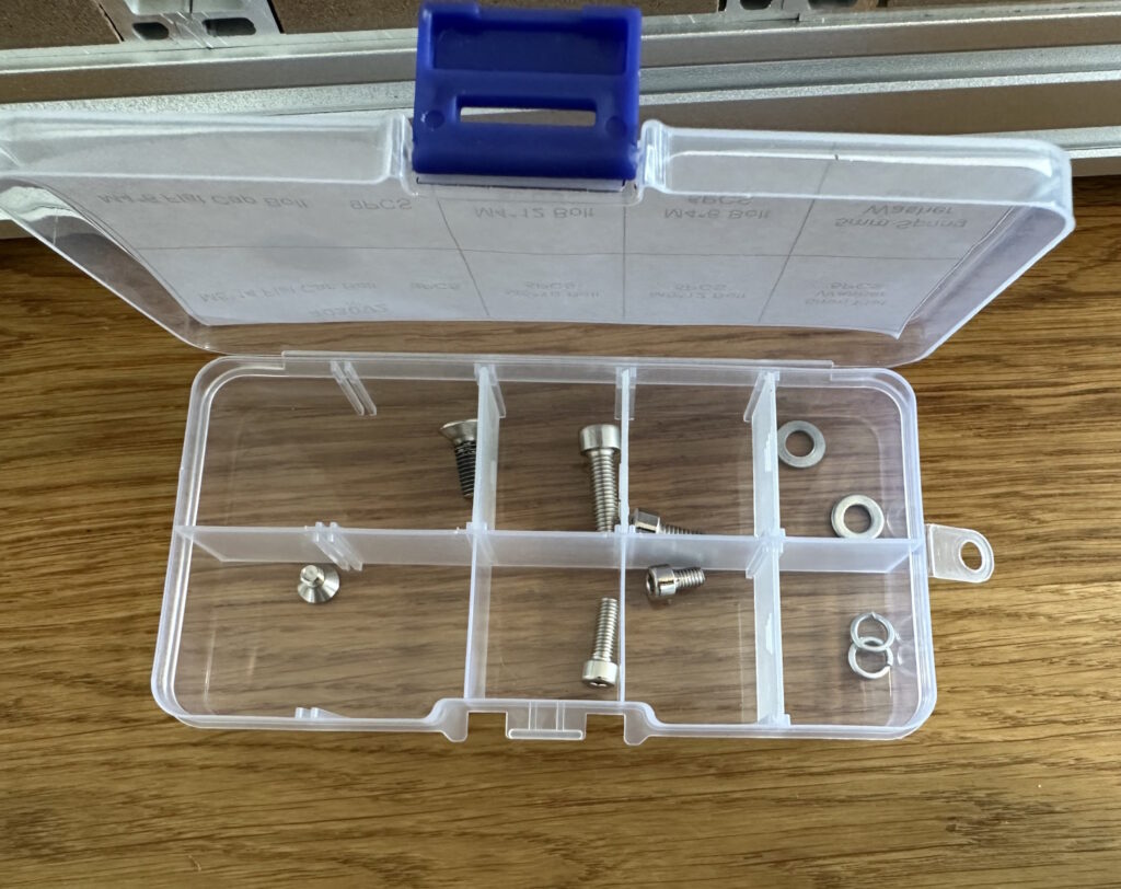
After assembly, by the way, there is one extra of each part in the accessory box, for all cases and eventualities.
Before we test run the machine, a few pictures of the control unit. Due to the names of the cables, the connection is dealt with relatively quickly, but the plugs are not interchangeable, so be careful. The switch positions of all stepper motors and the power supply should also be checked again:
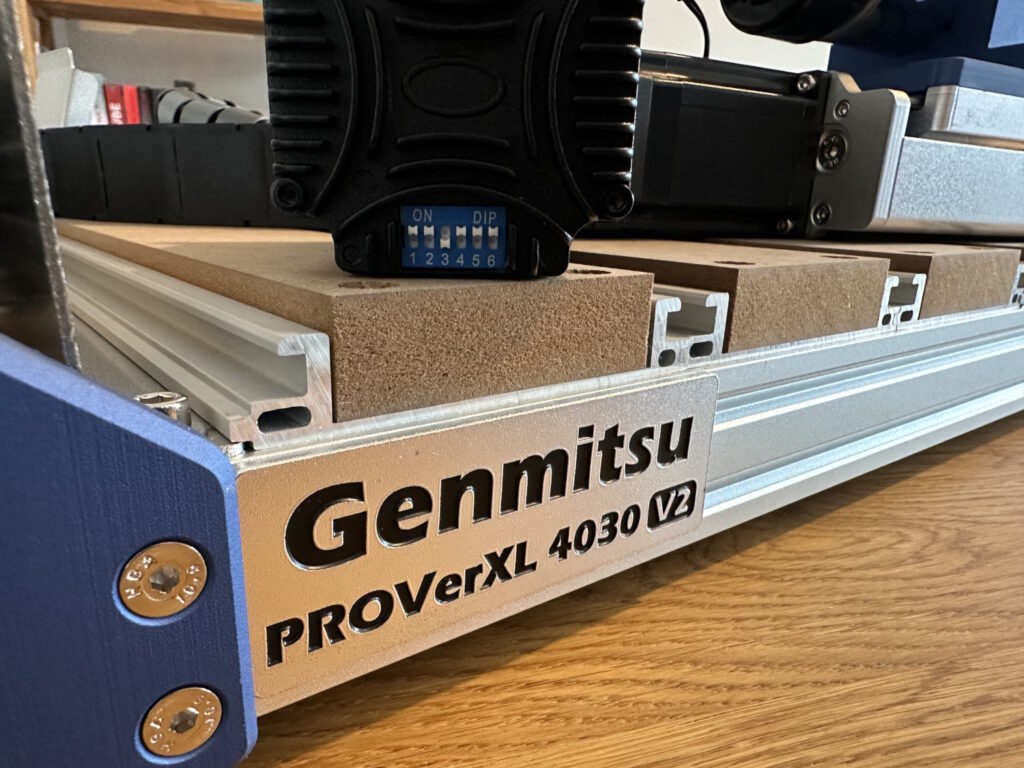
The small dip switches are to be set to the same configuration for all stepper motors, but in case of doubt, this can also be found in the manual. For the power supply, 230V should be selected:
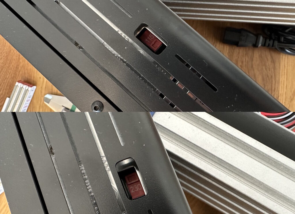
On the back is the matching IEC plug for the power supply, all other connections for daily use are located at the front of the control box. USB to PC, connection for a laser module and its switch, connection for the offline controller or the wireless module as well as the socket for the Z measuring probe.
Calibration
Normally, we had to calibrate every GRBL-based desktop CNC, whether milling or laser, once. In doing so, we check whether, as an example, the required 200 mm travel corresponds to 200 mm in reality. In fact, the values of the 4030 PROVer XL V2 were all perfect. No adjustment had to be made. In this article, we have described in more detail how to check and correct this directly using Open Builds Control and the included engraving cutter.
In the next step, we check how the bed relates to the axles. The measure itself is uninteresting, rather the difference between the values is the decisive factor. Measured simply in the corners and the middle of the bed using the Z probe.
| 78,728 (0,23) | 78,828 (0,33) | |
| 78,498 (0) | ||
| 78,698 (0,2) | 78,631 (0,133) |
Bed unevenness ex works
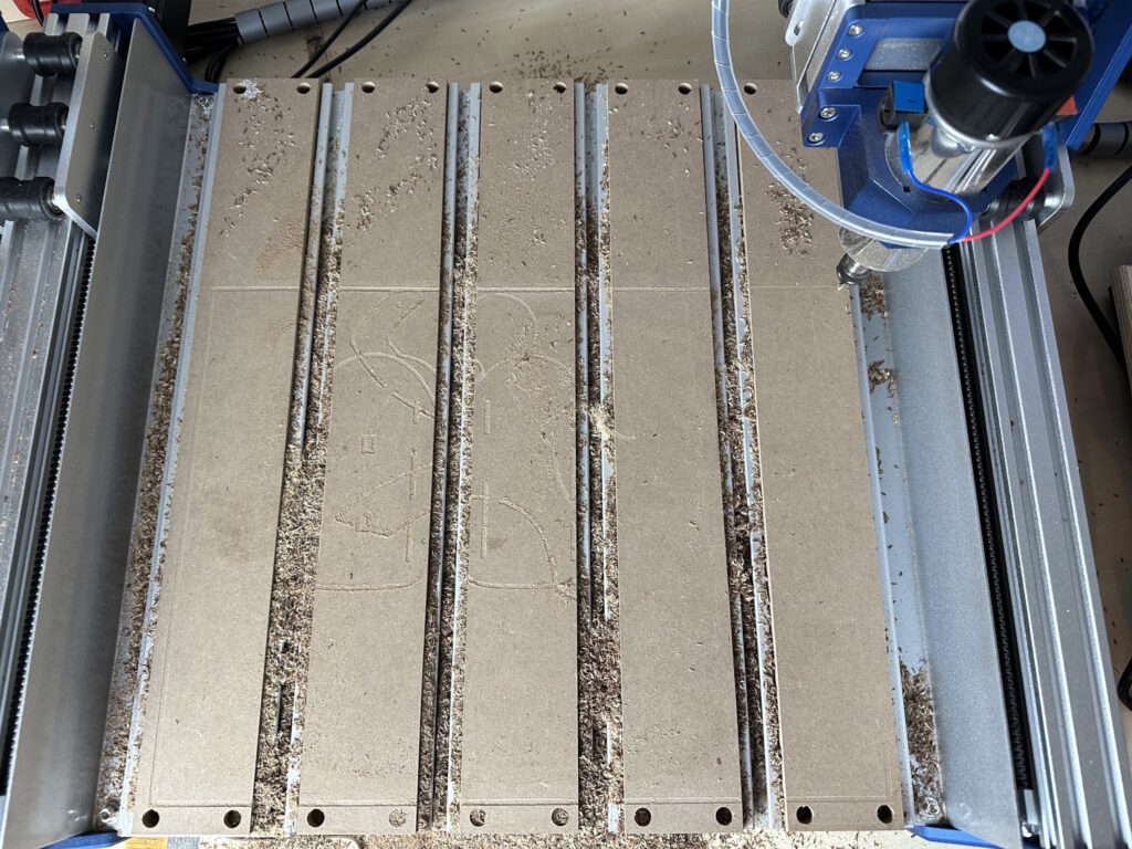
Once the bed has been overscheduled, the values look like this:
| 86,773 (0,035) | 86,755 (0,017) | 86,783 (0,045) |
| 86,743 (0,005) | 86,738 (0) | 86,765 (0,027) |
| 86,713 (0,025) | 86,698 (0,04) | 86,748 (0,01) |
Bed unevenness according to planning
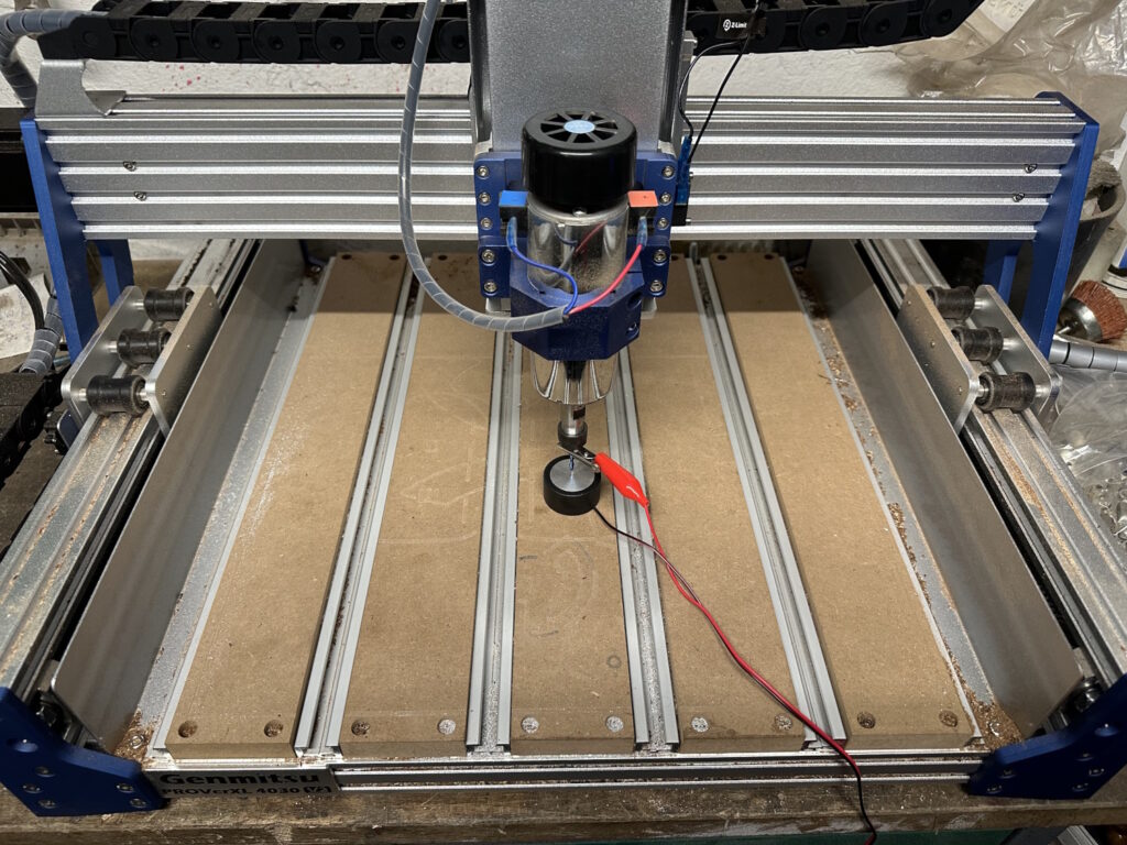
Since the bed of the 4030 PROVer XL V2 is rigid and the entire XZ bridge moves back and forth, the face milling cutter in the rear area unfortunately does not reach the last corner. A remedy here would be a glued-on spoilboard that is only mounted in the work area. Especially if you have planned several times and larger material is used, it will eventually rest on the back of the unreachable spoilboard. At a minimum, however, the limit switches could also be moved outwards. So from time to time the spoilboard should be turned, just plan the later rear part a little further beforehand.
In the previous picture, you can see not only the working area of 410 x 310 mm X & Y, but also that the bed sits higher on the left than on the right. Exactly for this reason, the bed should be straightened once. By the way, the height is limited to 108 mm by the underside of the entire Z axis. The travel is even larger at 120 mm. If there are strong milling marks when planning, you can also adjust the inclination of the spindle motor yourself - but this was not necessary for us. The milling marks are visible but virtually intangible.
As an aid, you can build a tool out of old milling cutters or simply glue two Allen keys together. It is only important to extend the lever so that the inclined position of the motor is clear. The tool is easily moved against the bed and should then be able to be turned around by hand with the same resistance. If there is no noise at one point, this side is too high, if it is difficult to go on at another point, this side is too low.
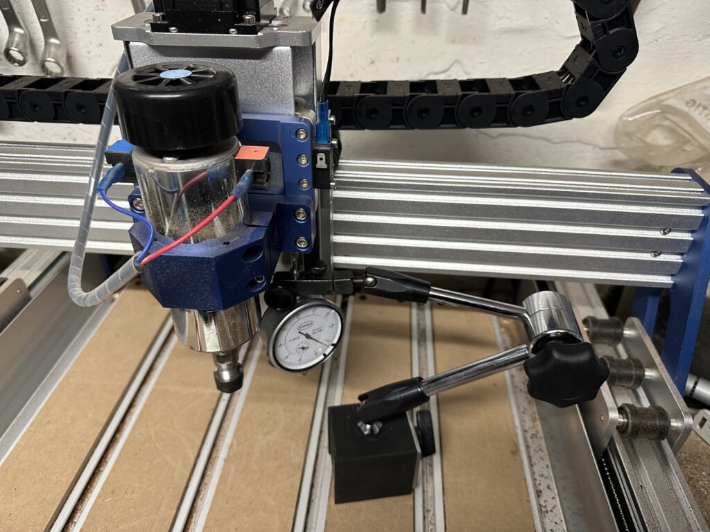
Using a dial gauge, I tried to show the flexibility of the axes, as well as backplay and repeatability:
| Axis | 3018 Per Game / Flex | 3020 Pro Max Game/Flex | 3040 Pro Max Game/Flex | 4030 PROVer XL V2 Game/Flex |
| X | 0,1 / 0,4 | 0,02 / 0,15 | 0,06 / 0,2 | 0,05 / 0,1 |
| Y | 0,1 / 0,4 | 0,1 / 0,25 | 0,1 / 0,4 | 0,03 / 0,1 |
| Z | 0,1 / 0,4 | 0,02 / 0,2 | 0,03 / 0,3 | 0,03 / 0,3 |
Values in mm
I applied the clearance using a dial gauge in the direction of the axis, measured. The milling machine moved 2 mm forward and 2 mm back to ensure that I ended up at the same initial value again. To measure the freewheel or backlash, I now drove 2 mm forward, 4 mm back and then 2 mm forward again. The dial gauge now shows a deviation from the initial value – the play in the drive system. Flex refers to the displacement as soon as external force acts on the axle. This is difficult to check in operation and was measured at rest. Unfortunately, I could not apply a standardized force, so this value is more of a rough direction. However, one should not ignore how much larger the 4030 is compared to the other two machines. Whereas the trapezoidal threads still clack noticeably when you move the axes back and forth manually, the ball screw of the 4030 does not allow this at all and does not emit any noise.
The first commissioning has thus been completed. Everything works, there are no cables in the range of motion, everything is set up and prepared in the best possible way – so the 4030 PROVer XL V2 is ready for its first use.
The limit switches or their attachment points can be minimally tuned for even more travel. Most of the time, you can't get much out of it – so that's not necessarily mandatory before the first test run. For the Z axis, 2 mm more are possible, so completely negligible. To do this, simply use the slotted holes of the rail and push them further back so that the ramps trigger the microswitch a little later. For X and Y, you can drill new holes in the angle plates and get another 12 mm in X and 10 mm in Y. This results in a working area of 422 x 320 x 122 mm. In Z, as already mentioned, attention must be paid to the 108 mm bridge height. So the Z way cannot always be fully used.
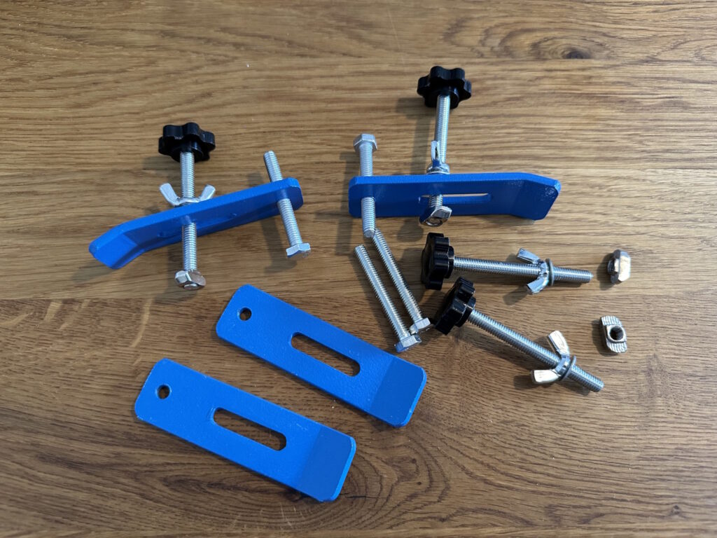
Quickly mount the clamps and you're ready to go. The assembly is described as shown on the right, but I like to turn the screw over so that it offers more support, after all, it is only a support point. Tightening is done by means of a wing screw. The T-slot nuts are shaped so that you can use them anywhere and don't have to pull them through the entire slot.