Wrriten by Dennis Heinze
Simulation
"Preview all tool paths" now shows the process and the final result as a simulation. In this step, preview images can also be created for potential customers, which can be highlighted with colors. By clicking "Close," we return to the overview of the tool paths and see that two paths have now been created: Pocket 1 Clearing and Pocket 1, Base, as two cutters were previously selected. Clearing or roughing is the coarse work, while Pocket 1 without additional is the finishing work with the 1 mm cutter.
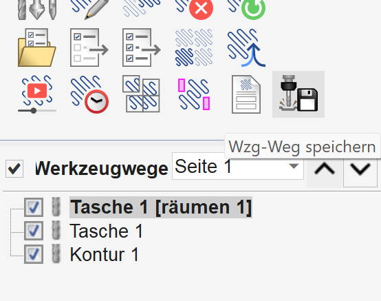
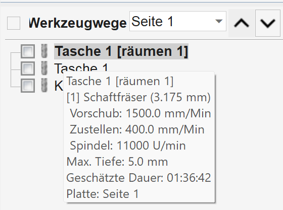
When hovering over Pocket 1 with the mouse, the cutting data appears accordingly; a double-click allows you to adjust the process again.
Contour
Contour 1 already shows the cutout of the sign. The outer vector is marked as a contour, and the contour tool path icon leads you to the following menu:
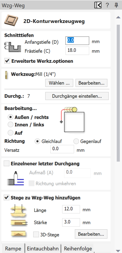
The menus look very tidy and, in my opinion, are easier to understand than, for example, Carveco Maker. Nevertheless, advanced functions and settings are included. To ensure our component is not completely cut out, we will add a few supports:
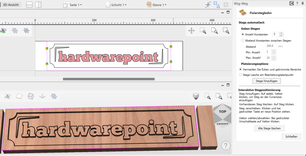
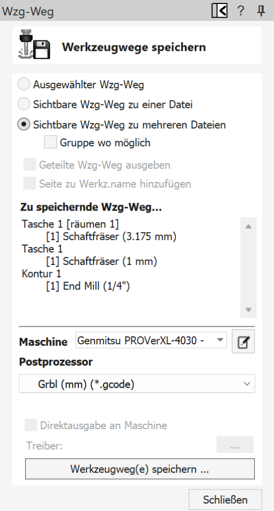
If the automated assignment is not effective, meaning the supports are not easy to remove later, they can also be freely positioned. Thus, the first test project is completed, and via "Save tool paths," these can be exported with the corresponding post-processor for our 4030 PROVer XL.
Export
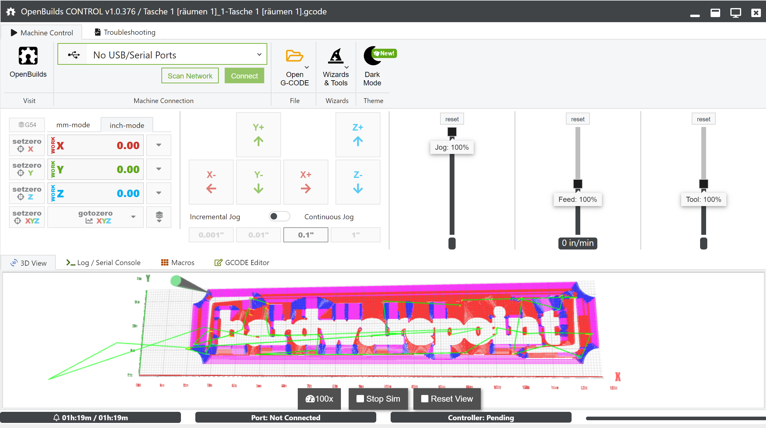
Three individual files are created, one for each tool used. With vTransfer, the code can also be sent directly to a connected milling machine; however, we use Open Builds Control and now also the wireless module and a tablet for control, more on that in the upcoming article.
Since the appearance with a simple pocket command is nothing special, I tried the V Carve function in combination with a 60° 6 mm V bit cutter. To speed up the process, a roughing pass with the regular 3.175 mm shaft cutter was done first, followed by the cutout using the contour function:
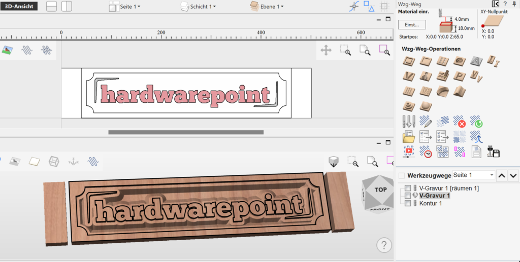
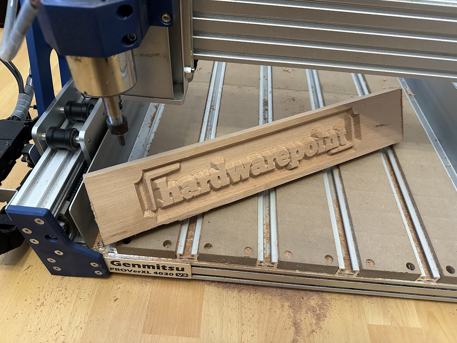
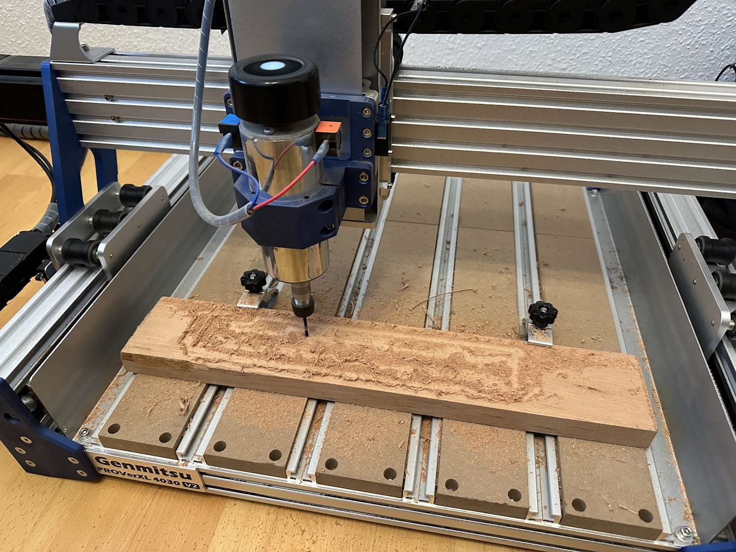
The preview looks interesting, so off to the 4030 PROVer XL; about 1 hour later, the finished part could be held in hand.
These were the first three tool operations, perhaps the simplest and also the most commonly used. Since the hwp logo is a simple 2.5D model, we want to test a real 3D model again before showing you more news in Aspire 12.
2. Project 3D Pike
Aspire comes with an extensive clipart collection. After the remnants from the previous project were still large enough for a 3D milling, I quickly selected something from the pre-installed models. The choice fell on a pike model; the image gallery shows the creation. The model is dragged and dropped from the templates onto our raw material, scaled a bit, and centered. While the 2D view does not really reveal much, the 3D view already shows the finished model. Tool paths are created using 3D roughing and 3D finishing passes. Then it went directly to the 4030 PROVer XL; also after 1 hour, the fish was milled out:
New in Version 12: Alongside the new interface design in Version 12, several new features have been introduced in Aspire, which we would like to briefly examine.
**Image Carving**: With the carving tool, images can be transferred into stylized V-carvings. This appearance can be interesting for some projects and can be created with just a few clicks. In the example, an image of a Datsun: The V-cutter also creates depths and a kind of 3D effect.
**Exclusion Zones**: Vectors can be drawn directly into the design, which will later be avoided by the cutter. For example, the position of the clamps can be defined as an exclusion zone, ensuring that they do not come into contact with the cutter. If the design conflicts with the exclusion zone, a corresponding message is displayed, allowing the user to redefine the exclusion zone.
**2D to 3D Tools**: In the past, Aspire already allowed importing 3D models or using clipart. However, it is now also possible to convert 2D vectors into 3D variants. The stars indicate the different variants, which can be finely tuned using a slider. Three modes can be selected, primarily affecting the top surface of the model: flat, pointed, or rounded. It is also possible to create a custom 3D transformation as a final function. This means not only simple shapes and texts, like in the example, can be transformed into a 3D model, but also complex 3D vectors. When external 3D models come into play, such as STL files from a 3D scanner, the software consumes a lot of hardware resources. At least, that was the initial thought, as the software struggled quite a bit. A look into the settings revealed that a software renderer was selected. Disabling this allowed rendering to occur natively on the graphics card. After a restart, everything ran smoothly. Aspire previously calculated primarily on the CPU, and even with small models, like the sheep as a single component, Aspire could push the CPU usage to 100% with an AMD Ryzen 7800 X3D. The situation can be improved by reducing details via the material tab or during job setup, but the issue is more about software rendering emulation rather than the hardware itself. For pure conversions of vectors and fonts, this is less of a problem. If necessary, one can also work in 2D view and switch to 3D preview only after the design work is completed. However, as mentioned at the beginning, disabling the software renderer should make it run smoothly if you encounter the same problem.
Also new is that adjustments to the project can be made directly in the 3D preview. There is no need to jump back into the 2D area. Since the sheep also has undercuts that cannot be implemented on a standard 3-axis CNC, the model looks a bit funky, but the images are only from a test run. With a two-sided processing, this can be somewhat mitigated, but such a sheep can only be produced with a lot of effort on a 3-axis CNC.
**V-Carving Inserts**: Aspire can generate a suitable insert for a V-carving with just one click. The main project carved in light oak can be completely upgraded with an insert in dark walnut wood. After both components are carved, the insert can be placed in the base and glued. After the drying time, the insert is simply planed, and the two types of wood should seamlessly transition into each other. The tool paths with mirroring and the corresponding distances can be created and generated in just a few minutes. The advantage is faster processing: in our example, 45 minutes compared to 1.5 hours for a V-insert versus a standard insert in the form of individual letters. Additionally, the processing is simpler since the insert is a single piece and allows for very fine work. Curvatures are sharp and not limited by the cutter radius, as the V-bit is also pointed at the bottom.
Conclusion
For every type of CNC processing, a design or CAD program and CAM software is needed to convert the design into understandable code for the cutter based on the available tools. With Aspire, Vectric has a software on the market that is very easy to learn yet offers an immense range of functions. The community around Vectric products, including VCarve, is large, allowing many videos on how-tos and design ideas to be found on relevant platforms. Vectric itself also provides many tutorial videos, making it quite easy for me to get started with Aspire. Previously, I often used the free version of Easel by Inventables, and I will likely purchase VCarve now, as I was convinced by its usability and functionality.




![[Part 2] How the SainSmart 3020-ULTRA Became the MVP of Our Robotic [Part 2] How the SainSmart 3020-ULTRA Became the MVP of Our Robotic](http://www.sainsmart.com/cdn/shop/articles/How_the_SainSmart_3020-ULTRA_Became_the_MVP_of_Our_Robotics_Workshop_1_275bb939-69dd-4373-9519-08c750a7a8fc.webp?v=1752228400)


