Written by Denis Heinze
Since our CNC for Dummies article is approaching its 3-year mark, it's time to explore more advanced CAD/CAM software. Previously, we reviewed Easel, Carveco Maker, and FreeCAD. Vectric's Aspire not only offers powerful tools for creating 2.5D and 3D designs but also generates the necessary toolpaths.
Versions
Aspire is Vectric's top-tier CAD/CAM software. They also offer Cut2D and VCarve in both Desktop and Pro editions, each varying in features and pricing. Aspire is priced over €2000, which might be steep for hobbyists, but VCarve at around €400 is ideal for casual users. All updates are included indefinitely without monthly fees, and upgrades are available by paying the difference.
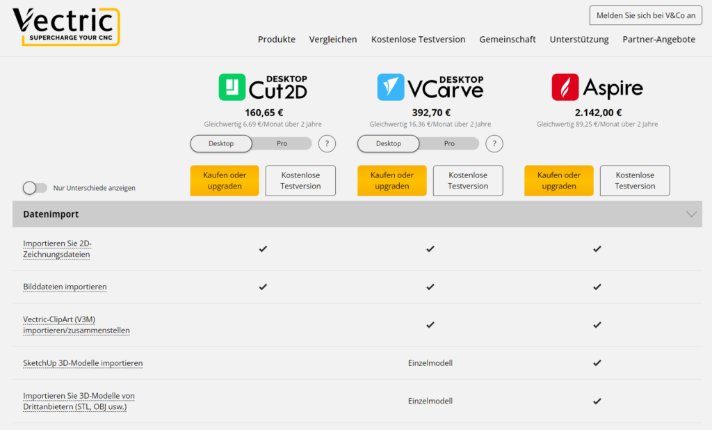
You can compare all Vectric tools and download trial versions on their official comparison page to find the best fit for your needs. For this article, we'll explore Aspire and create some designs using our Genmitsu 4030 PROVer XL V2. Aspire's high price is justified for professional use, while VCarve offers a great balance for hobbyists.
All updates for your version are included forever, including new major releases within the first 12 months. The current version is 12, and purchases now will include all 12.x versions and any future 13.x releases until June 2025. There are no monthly fees like Easel or Carveco Maker.
Upgrade options between Cut2D, VCarve, and Aspire allow you to pay only the difference. Additional downloadable cliparts, 2D/3D models, and textures are available to assist in your projects.
Installation
After purchase, download the approximately 500 MB software package from the V&Co portal and follow the setup instructions:
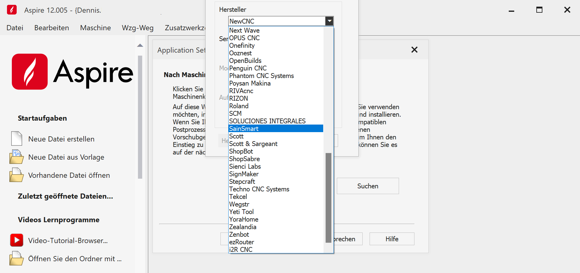
Once installed, the software links to your account and allows you to select your CNC machine, such as the pre-configured SainSmart Genmitsu 4030 PROVer XL V2. Ensure you choose the mm postprocessor for European machines.
Getting Started: Creating a Project
For beginners, we created a simple HardwarePoint sign. Instead of engraving the letters, we raised them using a V-bit to see the resulting effect.
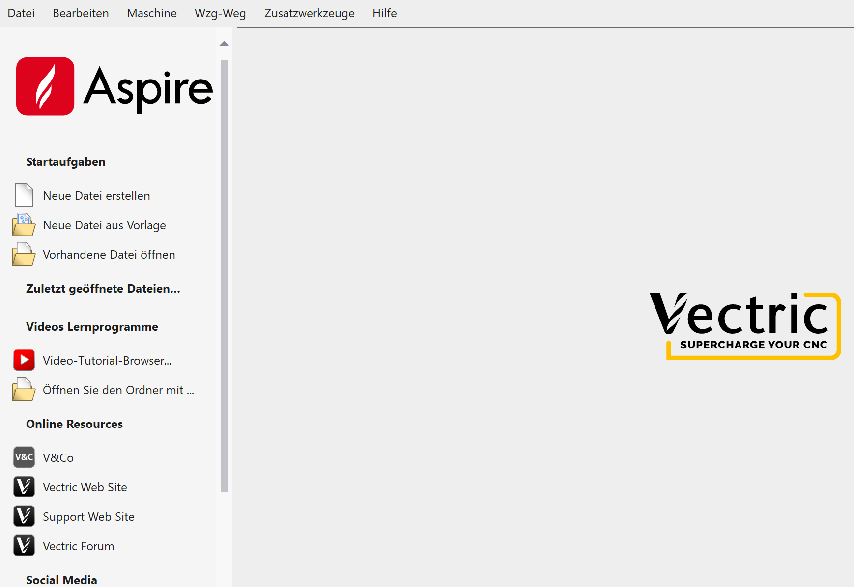
The main menu provides links to tutorials with detailed (English) videos that guide you through all features step-by-step, making it easy to follow along.
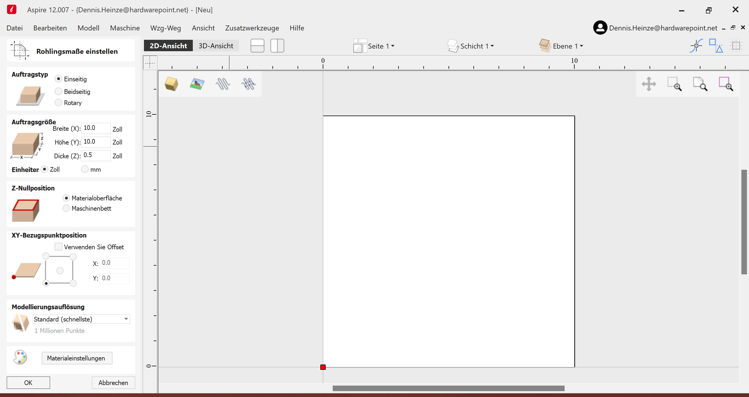
Start by creating a new file, specifying material size and units (mm). Adjust the Z-zero position based on your setup. Most settings default to the workpiece, but you can adjust if using multiple bits.
In the 2D view, draw shapes by clicking and dragging. Use the menu for precise measurements. Switch to the 3D view for detailed adjustments and accurate dimensions.
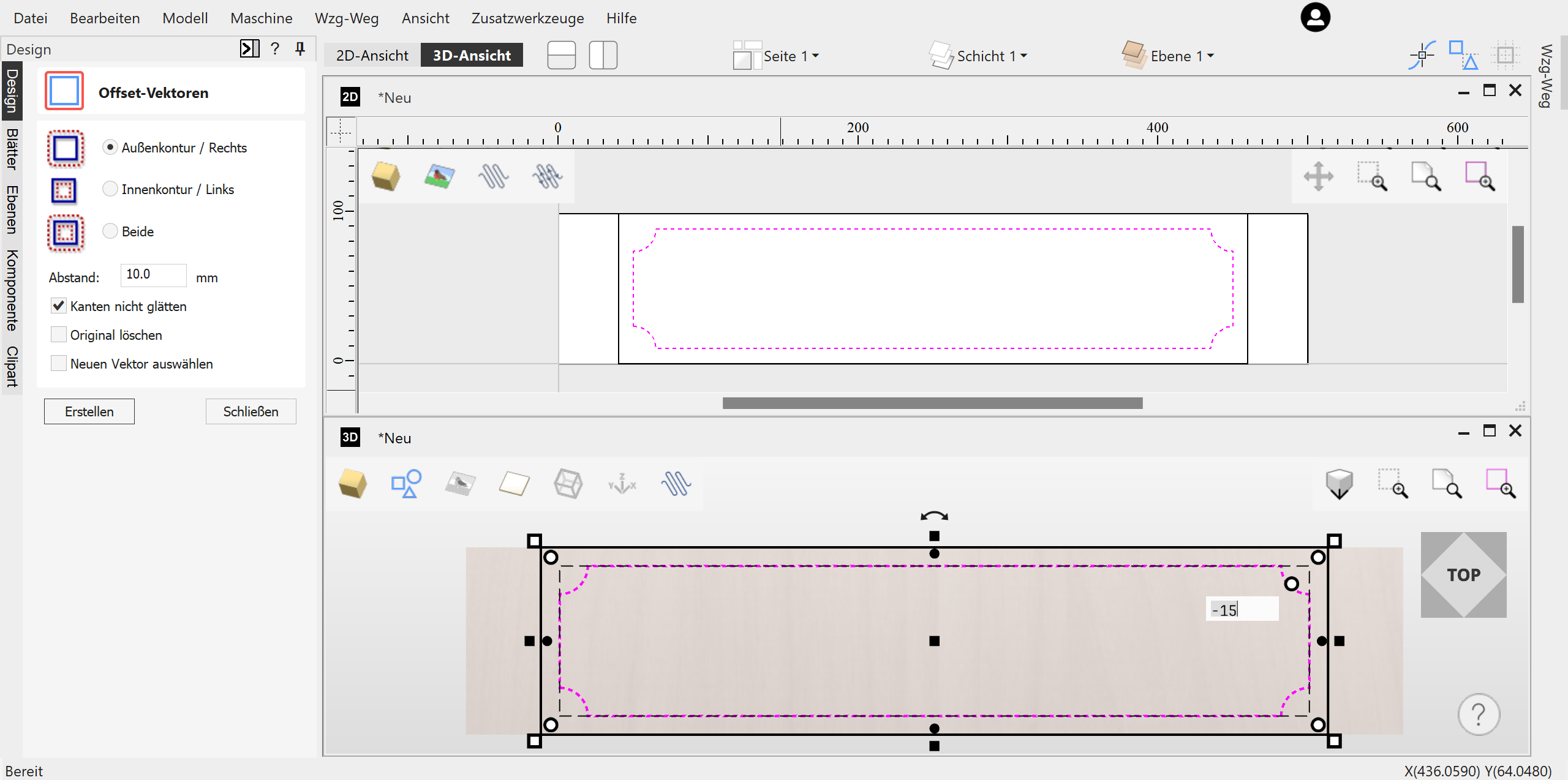
Align and offset vectors as needed. Convert bitmap images to vectors using the "Trace Bitmap" feature for toolpath creation.
Once satisfied with the design, generate toolpaths by clicking the arrow icon. Aspire translates your design into machine-readable language, ready for CNC machining.
Vectric Aspire's comprehensive features make it suitable for both hobbyists and professionals aiming to create intricate CNC projects.
For more details and visuals, visit the full article on HardwarePoint.
Toolpaths
To ensure that the design we just created— which, by the way, didn’t take 5 minutes to make—can be executed by the milling machine, appropriate toolpaths must be generated. This is the CAM (Computer Aided Manufacturing) part of the entire process, following the CAD (Computer Aided Design) phase.
Vectric Aspire offers the following toolpath operations:
- Contour Paths
- Pocket Tool
- Drilling
- Thread Milling
- Quick Engrave (for Drag-Bits)
- Inlays
- V-Groove Milling, Graver Pen, or V-Carve
- Photo V-Carve
- Carving
- Prism Milling
- V-Carve Inlays
- Rounded Corners
- Textures
- Chamfers
- Shapes
- 3D Roughing
- 3D Finishing
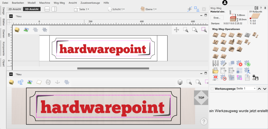
Additional modules can be downloaded as gadgets through "Add-Ons" or even developed by yourself:
Pocketing
We use the pocket tool to mill the area between the letters and the inner boundary, and then use the contour tool to cut out the component. Later, I chose a V-Carve instead of the pocket to try a different look.
The functions initially seem overwhelming, but you should take a look at each one individually. Aspire automatically selects the appropriate cutters for the function, and all parameters can be explained with images or additional menus. This makes the initial learning curve relatively easy. After experimenting a bit, the corresponding toolpath is simulated and can be previewed. The 3D view not only shows the tool's path but also how the workpiece will look afterward. This helps in understanding which modes create the desired aesthetics.
Back to the hwp logo. After drawing a frame over the hwp logo and the inner boundary with the left mouse button in the 3D preview window, these areas are highlighted in pink. Multiple selections in Aspire are done using the Shift key, not CTRL. Clicking on "Create Pocket Toolpath" opens the following menu:
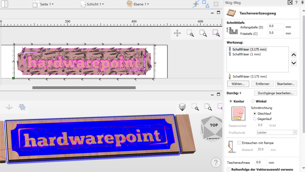
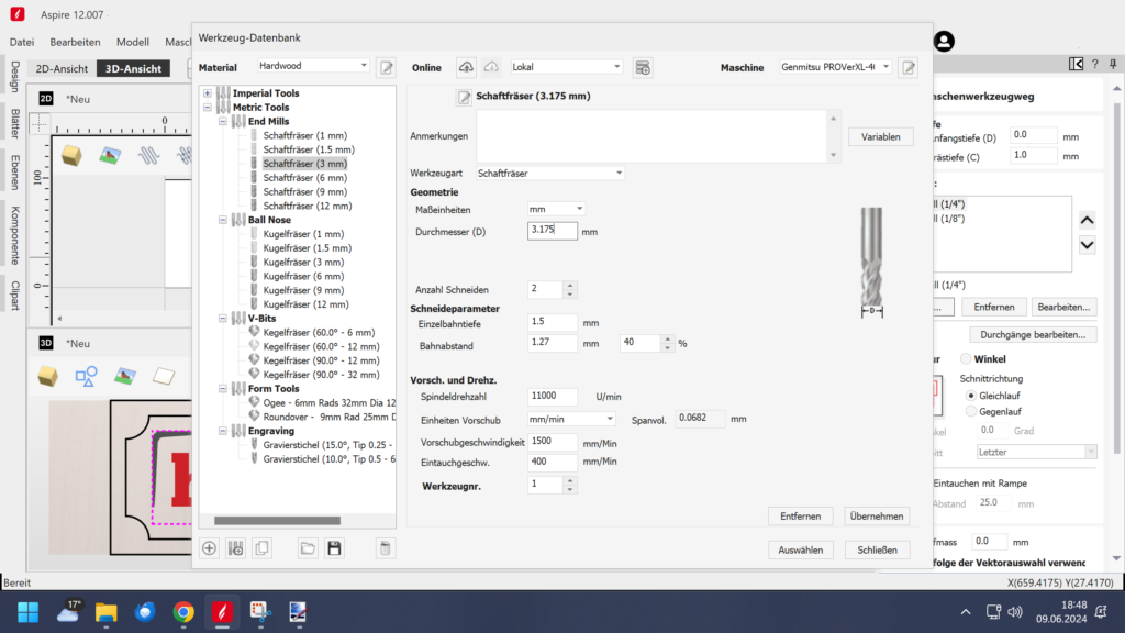
Tool depth C indicates how deep the letters should be milled from the top of the workpiece. Tools can be added via "Select"—for example, a 3.175 mm shank cutter for roughing and a 1 mm cutter for detailing that the larger cutter cannot achieve. Aspire then creates two separate toolpaths, allowing you to execute each tool individually.
Tools
The built-in tool database already includes classifications for both metric and imperial tools as follows:
- End Mills (Straight End)
- Ball Mills
- Ball Nose Mills
- Conical Mills
- Graver Pens
- Corner Radius Mills
- Profile Mills
These are differentiated for materials such as hardwood, softwood, MDF, and acrylic. Additional databases can, of course, be added, for example from tool manufacturers like SpeTools or Amana, who provide data.
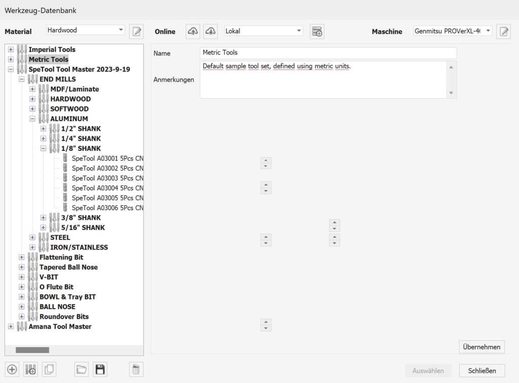
However, you can also create your own tools. Existing tools can be used as a reference, or you can choose to import values from other database entries during creation. This allows you to quickly create new tools and ensures that you are roughly on the right track with the cutting data.
Dimensioned images also show examples and corresponding specifications needed for creating tools, such as spindle speeds, depth per pass, overlap per path, and lead-in/out. After creating or at least selecting a tool, many standard cutters are already available, and by using "Select," the cutter is added to your job.
"Edit Passes" allows you to view and adjust the cutting depth per pass if you want to deviate from the parameters assigned by the tool/material combination. Metals are available in the material selection but not in the pre-installed tool database.
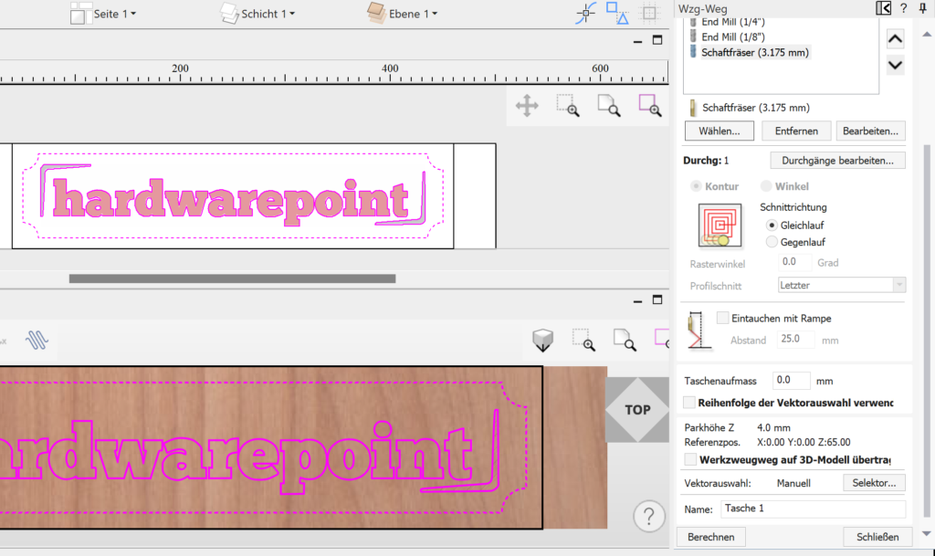
Contour milling allows the cutter to move from the center outward in a circle towards the final shape. For angles, the cutter moves from right to left, depending on the set angle. You can also choose a preceding or subsequent departure from the outer contour. As the menus change based on your selection, it's easy to understand what each function means, even if the terminology is unfamiliar at first—just experiment. Climb milling (where the cutter rotation and feed direction are aligned) primarily affects the stability of the mill and the finished surface quality. Climb milling demands more from the machine but provides better surface finishes. Generally, prefer climb milling for finishing and conventional milling for roughing.
The "Ramp Entry" checkbox reduces tool wear by angling the cutter between increments in depth, rather than plunging straight down.
The option "Transfer Toolpath to 3D Model" isn't needed for the example project, but it's a very helpful feature when 2D paths run over a 3D model, allowing them to adhere to and follow the 3D geometry.
Clicking "Calculate" generates the toolpath.
For more insights and advanced techniques in CNC design using Vectric Aspire, check out the second part of the article here.


